Tools Optimize Process and Part Quality
Aerospace and defense manufacturers are demanding shorter lead times, better quality, and lower costs from their suppliers. Oftentimes, the supply chain will default to delivering on a lower price to ensure consideration in the purchasing process. This mindset, competing on price, fails to fully appreciate the impact on product quality. And today, with price and delivery time being equal in a majority of purchasing decisions, product quality will be the ultimate differentiator. The pres-sure is not just felt by suppliers. Aerospace and defense companies demand the same from their in-house manufacturers as they do from their third-party suppliers.
Every individual manufacturing process has become a race to the finish line. At the end of that race, another one starts. Race after race places a tremendous amount of pressure on machines, programmers, setup personnel, operators, and tooling. Computerized programming and 3-D verification of CNC machine tool programs allow programmers to deliver a qualified instruction set to the shop floor. The CNC program should make a qualified part each and every time. But what happens when the parts are not to print specifications?
Inconsistencies due to machine tool wear and toolholder repeatability
To ensure a consistently manufactured and qualified part as well as reducing the amount of scrap, the fol-lowing should always be kept in mind. The entire production process requires a commitment to reproducibility and repeatability in order to deliver qualified parts. This production process includes everything from toolholders and cutting tools to coolant delivery and chip evacuation systems. Since delays are detrimental to your production plan, you need to empower the shop-floor personnel with the resources necessary to keep production downtime to a minimum and workpiece quality at 100%. Attention to detail on all fronts will help in achieving the ultimate production efficiency; zero scrap. The cost to address these details is minimal in comparison to the monetary losses of a cell not running at peak performance, or worse yet, down for maintenance.
As machine tool process speeds increase, safety at the ma-chine spindle is more important than ever. Higher speeds and feeds require the entire complement of tooling components to be managed as a unit. In aerospace and defense, where 100% success is required, knowing the accuracy, reproducibility, repeatability, and rigidity of the machine tool spindle, tool-holder assembly, and workholding assembly is critical.
Empower and resource your production team
Nonstop production increases the probability that your machine tools will require more maintenance. Undetected problems can damage the machine tool or introduce production stoppages to resolve problems with surface finish, tool wear, or dimen-sional correctness. The shop floor relies on the ability to get up-to-the-minute information on a machine tool’s performance as well as its ability to meet predefined conditions (e.g. spindle runout and drawbar force). CAD/CAM technology provides the programming staff with the tools needed to achieve first-part quality on the computer screen. Getting the same results on the machine tool can be a bit more challenging. When resources and time are allotted, your setup and operational staff will be able to achieve a scrap rate of zero, optimize tool life, and maintain machine tool health.
Necessities or accessories?
When you strive for perfection, what many consider machine tool accessories, become necessities. Having to get it right the first time and every time after that changes the formula for success. Not all variables in a CNC program can be debugged on a computer screen. Specifically, attention should always be paid to problems associated with the machine spindle, toolholder assembly, and workholding assembly. When unaddressed, these variables can create endless production problems related to positional tolerances, feature size, surface finish, and tool life. Understanding the repeat-able accuracy and rigidity of your machine tool accessories will help to implement processes capable of producing quality workpieces each and every time.
Manage your machine spindle
Machine tool spindles must be cared for properly. You can extend the amount of time it takes before a machine goes down for maintenance or repair through due diligence. Start with the machine tool spindle, as its condition directly affects machine tool performance. Everyone around a machine should be encouraged to help manage the spindle. Tools and gages should be available to allow your staff to clean, then inspect the retention knob pull force, amount of dynamic runout, accuracy of mating surfaces, and cleanliness of mating surfaces.
Spindle rigidity also has a direct effect on the machine tool so it is a good idea to acquire a retention knob pull-force gage for testing your spindles. Test the drawbar force on a regular basis to make sure it does not fall below acceptable levels. Low drawbar forces affect tool life and surface finish as well as the health of the machine tool. A lack of rigidity between the spindle and the toolholder may result in friction that will degrade the surfaces of your toolholder and spindle, leading to eventual spindle failure.It is also desirable to frequently check the dynamic runout of your machine spindles using a precision gage bar, a perfectly concentric steel cylinder that measures the spindle rotation against its centerline. Lower spindle runout will yield an in-crease in machine tool performance, extend tool life, and most importantly, extended your spindle’s life. Visual inspection and gages should also be used to check the spindle geometry.
Excessive spindle wear can only be corrected by regrinding, so proactively manage your machine tool’s spindle health. Ma-chine spindles must be kept clean. Any particles or contamination that gathers between the mating surfaces will cause wear. Use cleaners frequently to wipe clean the contact surfaces of the spindles and toolholders. Cleaning your spindles should be a mandatory part of your shop’s day-to-day operations.
Manage your toolholder assembly
The relationship of the tool to the toolholder is just as important as the relationship of the toolholder to the spindle. Unlike spindles, which operate within the controlled environment of the machine, toolholders can be exposed to many pollutants all around the shop. During storage and between uses, toolholders run a high risk of picking up oils, dust, and other particles that can contaminate their surfaces. Toolholders can also be damaged during assembly and disassembly if improperly handled or processed. Cleaning the exterior of your toolholders is an important step before placing them into your toolchanger or spindle.Before loading a cutting tool into a machine, several factors may need to be qualified. The process of assembling a tool can introduce variables. Off-line tool presetters can be used to locate runout in tool assemblies outside of the machine spindle and qualify their location.
Cleanliness is important
In order to control the variables, it’s best to have clean components that are geometrically correct. Cleanliness is critical to achieving maximum tool life and material removal rates. The toolholder is purposely designed to hold the tool with sufficient clamping force to overcome the forces of the cutting operation and deliver the tool to the spindle centerline. Both of these functions can be degraded by many forms of contamination. Reductions in gripping strength and deviations from centerline will lower tool perormance. All toolholders have a better chance of delivering the tool to the proper location and holding them firmly when components are clean and free of contamination. Complex toolholders such as collet chucks should be completely disassembled and cleaned between uses. Wipers are available to clean the internal surfaces of the chuck body and the spring collet should have contamination removed with cleaning systems such as ultrasonic or high-pressure washers. Components need to be clean before assembly begins.
Tool assembly devices are available to assist in safely grip-ping toolholders. Avoid serrated grippers or loose fits that can easily scar tools and toolholder shanks. When a balanced tool is required, there are two approaches to delivering a qualified tool to the spindle. The first approach uses precise, balanced components. If everything is clean and in proper operating condition, components can be assembled and sent directly to the machine tool. If the toolholder components and cutting tool are manufactured for a lower level of precision, they can be assembled and balanced offline.
Manage your machine workspace
Workpiece handling needs to be treated the same way as tool holder assemblies. If you need a large number of tools available on-demand to meet all of your production needs, you either expand your toolchanger or change out the toolholder assemblies in the carousel. Similarly, if you need a large number of workholding devices to produce all of your products, you will need to swap out workholding devices or add machine tables. In order to control workpiece location and reduce change-over times, manufacturers are abandoning native handling solutions that are delivered by the machine tool. T-slot tables and end stops have traditionally lacked in providing a speedy and accurate interface for workholding.
Pallet pools on horizontal machining centers have gained approval. For companies that cannot duplicate machine tables, it is desirable to have the workpiece handling system positioned and clamped in a way that would allow the production process to commence without having to indicate in the handling device. Most companies choose to retrofit a quick-change positioning and clamping system to their machine table to facilitate these changeovers. These workholding systems need to provide fast, accurate, and rigid positioning and clamping. The most common quick-changing machine table setup systems are grid plates, zero-point clamping systems, and shuttle tables.
Grid plates provide a repetitive series of accurate bushing locations that accept positioning pins to locate work. These positioning locations are intermixed with threaded locations that provide a means of attaching clamps to hold the work-piece or workholding device with sufficient rigidity for the production process.Zero-point clamping systems combine positioning and clamping into a single process. A retention knob with a geometric reference datum is appended to the workholding device or workpiece. The clamping process draws the retention knob into a ground reference for simultaneous positioning and clamping. Small workspaces can be addressed with a single retention location. Larger components are addressed with multiple clamping locations.
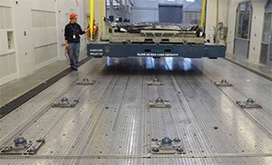
Janicki Industries (Sedro-Woolley, WA) implemented the BIG Kaiser Unilock zero-point system to allow workpieces to be preset onto their worktables outside of the machine enclosure. Machine downtime for setup changes is limited to the crane-in and crane-out time.Growing in popularity are shuttle tables which consist of a track mechanism connecting the machine table through a rail system to a table storage position. One table is available for setup while one is being machined.How much more spindle time is available per day? CNC machine tool efficiency is all about managing the components that need to come together in proper alignment. Your operational staff already has the skill set to implement a management procedure for the machine spindle, toolholder assembly, and workspace. Your programming department can link all of the pieces together. All you have to do is provide the resources and turn over responsibilities to your employees to deliver production uptime and quality.


¿Te pareció interesante o útil? Haznos saber tu opinión agregando tus comentarios o preguntas a continuación.