What is the effect of fatigue stress on the condition of tool holders?
How can fatigue stress in tool holders be controlled?
Últimas Publicaciones
Anatomía de un portaherramientas: Todo lo que necesita para el éxito en la sujeción de herramientas
Puntos Clave
-
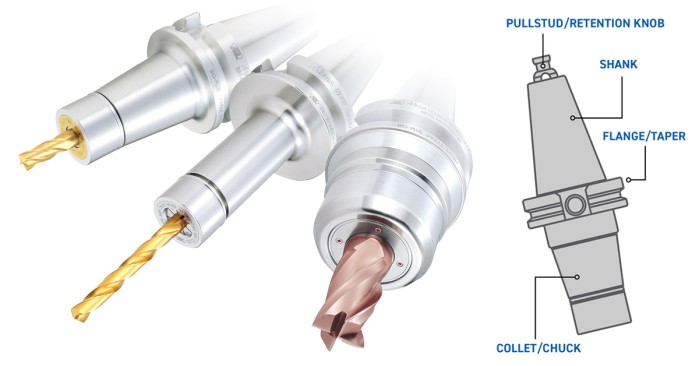
Aprenda cómo cada parte de un portaherramientas contribuye a la precisión del mecanizado, desde el perno de sujeción hasta el vástago, la brida y el portacortadores o mandril.
-
Comprenda qué buscar al seleccionar un portaherramientas, incluida la capacidad de contacto doble, la coincidencia de tolerancias del husillo y la calidad de fabricación.
-
Descubra prácticas de mantenimiento que protejan los portaherramientas contra daños y desgaste, garantizando un rendimiento a largo plazo y una calidad constante de las piezas.
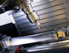
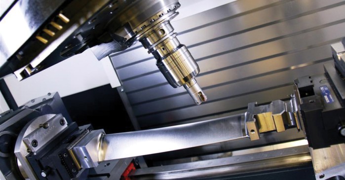
A medida que la industria metalúrgica evoluciona con velocidades más rápidas, materiales más difíciles de mecanizar, tolerancias más estrictas y costos operativos más altos, la optimización continua se vuelve esencial. Las máquinas, herramientas, procesos, automatización y capacitación de operadores juegan un papel importante. Pero las mejores máquinas y operaciones solo son tan buenas como la interfaz entre el husillo, el portaherramientas y la herramienta de corte.
En este artículo, comenzaremos desde el principio explorando todo, desde la anatomía básica de un portaherramientas hasta los criterios de selección y mantenimiento.
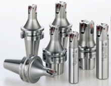
¿Cuáles son las partes de un portaherramientas?
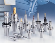
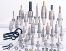
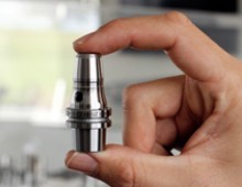
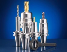
Si tienes conocimientos básicos de mecanizado, sabes que un portaherramientas es exactamente lo que parece: el componente que sostiene de manera segura una herramienta de corte en su lugar dentro de la máquina mientras el husillo gira y las virutas vuelan. Profundicemos en la anatomía del portaherramientas.
Espiga de tracción / Pomo de retención
Las espigas de tracción, a veces conocidas como pomos de retención, son sujetadores en la parte superior del portaherramientas que mantienen la herramienta firmemente unida a la barra de arrastre de la máquina durante las operaciones de corte. Este suele ser un elemento olvidado en la configuración del portaherramientas, pero la presión está aumentando sobre este componente vital. A medida que aumentan las velocidades del husillo y las fuerzas de corte, también aumenta la presión de sujeción sobre la espiga. Las espigas defectuosas, desgastadas o de baja calidad pueden generar problemas de precisión en el mejor de los casos, o desastres en el peor.
Aquí está la razón: los conjuntos de agarre de la máquina herramienta generalmente consisten en arandelas Belleville apiladas que se comprimen bajo carga. Si la superficie de la espiga no es correcta, las fuerzas de retención variarán; incluso una diferencia de solo 0,004” en la geometría o la superficie de contacto puede afectar significativamente la fuerza de sujeción y la precisión del posicionamiento.
En otras palabras, no basta con sacar cualquier pomo de retención de la estantería. Como dicen nuestros expertos en portaherramientas: “Solo eres tan preciso como tu componente menos preciso”.
Asegúrate de elegir una espiga diseñada específicamente para la máquina a la que se conecta, inspecciónala por desgaste y reemplázala según las recomendaciones del fabricante. Por último, la instalación correcta del pomo de retención (con una llave de torque) es clave. Asegúrate de que el pomo no deforme el extremo pequeño de la espiga cónica.
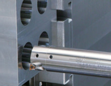
Espiga / Conicidad
La espiga del portaherramientas, o conicidad, conecta el portaherramientas con el husillo de la máquina. Un ajuste firme y seguro es muy importante para la precisión. El estilo, el ángulo de conicidad y el tamaño de la espiga deben coincidir con el tipo de husillo de la máquina. Por ejemplo, los sistemas CAT y BT presentan espigas cónicas pronunciadas. Los portaherramientas HSK utilizan una conicidad corta y hueca con contacto facial para precisión a alta velocidad, mientras que CAPTO presenta una interfaz cónica poligonal diseñada para modularidad y alta rigidez.
Los portaherramientas tradicionales de conicidad pronunciada están diseñados para aplicaciones de gran carga, siendo ideales para herramientas más grandes y máquinas que operan a velocidades más bajas. Por otro lado, los portaherramientas cilíndricos HSK pueden ser ideales para micromecanizado y altas velocidades.
Consulta la Parte 3 de nuestro ebook Intro to Tool Holders para más información sobre los tipos de interfaces husillo/portaherramientas.
Como con todos los componentes del portaherramientas, las espigas deben estar libres de imperfecciones y fabricadas con estándares rigurosos para asegurar los mejores resultados de mecanizado. Inspecciona visualmente y siente la espiga. Debe ser lisa, sin rebabas y con acabado espejo.
Brida
La brida es el “labio” visible del portaherramientas que asegura que encaje y se alinee en el husillo, proporcionando estabilidad adicional.
No basta con tener un contacto estrecho entre la conicidad del portaherramientas y el husillo: un buen portaherramientas también debe asegurar el contacto entre la brida y el husillo. Con este contacto dual, verás una mayor rigidez de mecanizado debido al mayor diámetro de contacto de la cara de la brida. Pero cuidado: no todos los portaherramientas de contacto dual son iguales.
Para los portaherramientas estilo CAT, la integridad de la brida en V es esencial, especialmente cuando se usan con cambiadores automáticos de herramientas. Las bridas finamente rectificadas no solo aseguran mayor rigidez, sino también cambios de herramienta más precisos y repetibles.
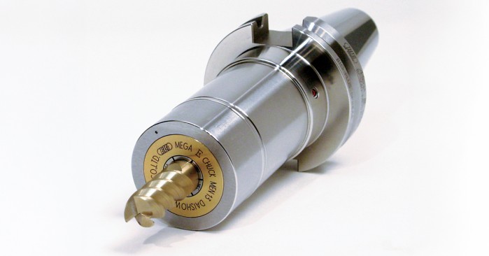
Portacolettes / Mandril
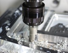
El portacolettes o mandril, según el tipo de portaherramientas, es el componente que mantiene la herramienta en su lugar y la estabiliza durante el corte. Un portacolettes es como un collar alrededor de la herramienta, ejerciendo fuerza de sujeción al apretarlo. Un mandril asegura la herramienta mediante sujeción hidráulica, ajuste por contracción o mecánica. Mientras que los mandriles de taladro pueden usar mordazas, la mayoría de los mandriles de alto rendimiento para fresado no lo hacen.
Los mandriles ofrecen mayor versatilidad y simplicidad, pero a costa de la precisión. Pueden ser adecuados para aplicaciones de gran carga donde la precisión a nivel de micrón es menos crítica. Los portacolettes, por otro lado, ofrecen mayor precisión y mínima excentricidad, gracias a un agarre más uniforme de la herramienta. Como desventaja, los portacolettes deben dimensionarse según la aplicación específica, requiriendo un inventario más grande y múltiples cambios conforme varían los trabajos.
Consideraciones sobre el portaherramientas
En la sección anterior, mencionamos algunos de los factores que influyen en la selección del portaherramientas, incluyendo el sistema de husillo y la elección entre portacolettes o mandril. Pero elegir el tipo de portaherramientas es solo la mitad de la batalla. A continuación, debes determinar cuál proveedor de portaherramientas es el mejor.
Debido a que los portaherramientas juegan un papel tan vital en el éxito de tus operaciones de mecanizado, tiene sentido invertir en portaherramientas premium que mejoren, en lugar de perjudicar, la precisión, la calidad de las piezas y la vida útil de las herramientas. Pero, ¿cómo sabes qué portaherramientas cumplen con estos requisitos? Aquí hay algunas preguntas para hacer:
¿Mi proveedor de portaherramientas tiene realmente herramientas de contacto dual?
Los portaherramientas de contacto dual crean contacto no solo entre el husillo y la conicidad del portaherramientas, sino también entre la brida del portaherramientas y la cara del husillo. Esta mayor rigidez beneficia el acabado superficial, la precisión dimensional, la vida útil prolongada de la herramienta, la repetibilidad del ATC y más.
Como se mencionó anteriormente, algunos proveedores afirman que sus portaherramientas son de contacto dual, pero ten en cuenta que los sistemas de husillo BIG-PLUS (el diseño original de contacto dual) solo proporcionan contacto simultáneo en la conicidad y la brida si están licenciados para BIG-PLUS. Sin la licencia, carecen de los calibres y tolerancias exclusivos para lograr este ajuste crítico.
¿Cuál es la tolerancia AT del portaherramientas?
La tolerancia AT se refiere a la clasificación de tolerancia de la conicidad del husillo definida por el fabricante de la máquina herramienta. La mayoría de los husillos de máquinas herramientas se construyen con una tolerancia AT1, y rectificar los portaherramientas a una tolerancia AT2 suele ser ideal. Sin embargo, muchos fabricantes rectifican a una tolerancia AT3, dejando un espacio de contacto que debilita la rigidez y la precisión.
¿Cuáles son los estándares de fabricación (y materiales) de mi portaherramientas?
Esta pregunta se aplica a todo el conjunto del portaherramientas, incluidos los pomos de retención, portacolettes y tuercas. En BIG DAISHOWA, nos aseguramos de que nuestros portaherramientas cumplan con los más altos estándares:
- Rectificado de todos los componentes con tolerancias precisas y acabados espejo
- Medición e inspección manual de los componentes (a veces dos veces)
- Uso de acero para herramientas de alta calidad (H13) en portaherramientas, portacolettes, tuercas y pomos de retención
- Agregado de la fecha de fabricación “born-on” en los pomos de retención para reemplazos oportunos
- Realización de toda la fabricación, tratamiento térmico y rectificado internamente para control total del proceso

Cómo mantener tu portaherramientas para un rendimiento máximo
Tienes toda la información que necesitas para elegir el portaherramientas perfecto para el trabajo. No descuides el mantenimiento y la limpieza. Ambos son esenciales para un rendimiento a largo plazo.
Limpieza del portaherramientas
Mantén herramientas de limpieza del husillo, conicidad y orificio a mano para eliminar virutas, residuos de refrigerante y otros contaminantes. Esto previene daños y corrosión, prolonga la vida útil de la herramienta y el portaherramientas, y asegura un contacto óptimo entre los componentes.
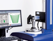
Inspección del portaherramientas
Las inspecciones regulares evitan que pequeños problemas se conviertan en grandes. Busca abolladuras y muescas en el portaherramientas; incluso los rayones aparentemente menores en la conicidad pueden reducir la precisión y causar retrabajo o desecho de piezas.
Lubricación
Lubricar las partes clave del portaherramientas, incluidos portacolettes y tuercas, reduce el riesgo de óxido y corrosión y asegura un funcionamiento suave. Sigue las recomendaciones del fabricante y utiliza lubricantes de alta calidad.
Almacenamiento adecuado
La forma en que almacenas los portaherramientas cuando no están en uso afecta el rendimiento. El polvo, los residuos y la humedad pueden acortar la vida útil del portaherramientas. Guárdalos en sistemas de almacenamiento cerrados y organizados, clasificados por tipo y tamaño para fácil identificación y prevención de daños.
La sujeción de herramientas nunca debe ser un pensamiento secundario en la fabricación de precisión. Elige los portaherramientas correctos y te proporcionarán la rigidez, baja excentricidad y precisión que necesitas. Son uno de los factores más determinantes en la calidad de las piezas, productividad, vida útil de la herramienta y éxito general del mecanizado.
Categorías
¿Te pareció interesante o útil? Haznos saber tu opinión agregando tus comentarios o preguntas a continuación.
Comments

BIG DAISHOWA Inc.
Mié, 02/07/2025 - 09:28There are two types of fatigue to consider. Cyclical loading of the assembly during side loaded cutting operations and repetitive stress that is unavoidable like actuating the holder during cutting tool changes or transferring the tool into the machine spindle. The stress on an item like a pullstud is consistent but repetitive and must be managed by timed replacement. Stress on the cutting tool clamping system can be reduced with proper assembly processes but monitoring is required for both runout and clamping. For example, bearing races in collet chuck clamping nuts reduce physical wear and offer consistent clamping and runout over longer periods of time vs. a solid clamping nut. Cyclical fatigue can only be managed with holder material selection and operation parameters. Through hardened tool steel holders like shrink fit and hydraulic suffer more from this type of wear over the more traditional case hardened alloys for most other holder types. The balance of speed and force required for the application and the assembly Length:Diameter will generally set the cutting limits. Lower side forces will reduce the potential base holder wear but could limit productivity.


Diment Gershman
Mié, 02/07/2025 - 06:42