Latest News


Accessories in Action

Machine tool accessories can offer economical solutions to many tooling and machine setup issues. Used in combination with a machine that delivers the speed and features a shop needs, accessories can help improve productivity and reduce machine failures. This article examines the benefits of several key accessories, including spindle maintenance tools, toolholder maintenance tools, covers, indicator stands, chip fans, tool assembly devices and specialty workholding devices.
Managing the Spindle
The spindle directly affects any machine’s performance, so it should be regularly cleaned and checked. A spindle maintenance checklist should start with inspection of:
- retention knob pull force,
- amount of dynamic runout,
- accuracy of mating surface, and
- cleanliness of mating surface.
Use a retention-knob pull-force gage to test the drawbar force on a regular basis. Service is required if the drawbar force falls below the minimum level stated by the machine builder. Continual operation with low drawbar force can lead to poor surface finish and tool life and increase the chance of damaging the toolholder and spindle.

Dyna Force Retention-knob Pull-force Gage
Managing spindle accuracy is critical to achieving superior part quality and extending spindle and tool life. To ensure spindle performance, runout must be controlled. Regular inspection with a precision gage bar can help identify potential problems and reduce downtime, spindle repairs and tool and toolholder damage.
A gage bar tests runout and spindle accuracy (see photo on page 70-S). It is a perfectly concentric steel cylinder that measures spindle rotation against its centerline. Lower runout increases output and extends tool and spindle life. Use visual inspection and gages to check spindle geometry. The internal geometry that establishes the spindle centerline needs to be free of defects and contamination. For dual-contact toolholding solutions, the spindles face must also be clean and properly maintained. As the spindle is an interchangeable interface for all toolholders, a damaged toolholder can transfer defects to the spindle and a damaged spindle can corrupt toolholders. Excessive spindle wear can only be corrected by regrinding or replacement.
The optimal operating environment for a machine spindle is free of dirt, oils and other contaminants. Cleanliness directly affects accuracy, and dirt can degrade rigidity of the machine tool/toolholder assembly. Particles and other contaminants cannot be allowed to gather between the two mating surfaces.
Spindle cleaners help maintain spindle precision and prolong machine tool, cutting tool and toolholder life. Use spindle cleaners several times a day to wipe spindle contact surfaces. Implementation of a rigorous spindle-cleaning schedule will have virtually no negative impact on machine tool output.
Managing Toolholders
The relationship of the tool to the toolholder is just as important as the relationship of the toolholder to the spindle. Unlike spindles, which can operate within the controlled environment of a machine, toolholders are exposed to many pollutants. During storage and between uses, toolholders can be contaminated by oils, dust and other particles. The toolholder’s exterior should be cleaned before it is placed in a toolchanger or spindle.
Dyna Test Precision Gage Bar
External toolholder taper cleaners are available for most common spindle types. HSK, CAT and BT toolholders can have their contact surfaces quickly wiped clean.
Prior to tool insertion, internal toolholder cleaners should be used to remove contaminants from surfaces that contact the cutting tool. Multiple cleaners are available for various toolholder styles, including shrink fit, side lock and milling chucks.
All toolholders have a better chance of delivering the tool to the proper location and holding it firmly when components are clean. Complex toolholders such as collet chucks should be completely disassembled and cleaned between uses.
Wipers are available to clean the internal surfaces of the collet body (see photo on page 72-S). The spring collet should have contamination removed with ultrasonic or high-pressure washers. Nuts should also be cleaned to assure uniform load pressures on the spring collet.
Inside the Enclosure
T-slot covers are protection plates that prevent chips and coolant from collecting inside a machining center’s T-slots. When slots are not being used, these covers can be easily moved into place to keep T-slots clear of debris. These aluminum inserts are simple to remove and deliver a clean machining surface to work from when changing setups. They also keep chips on top of the table where they can be easily brushed or washed into the chip conveyor system.
Certain industries, such as aerospace and medical, require near perfection in machining. Articulated stands can help deliver that for multiple applications by combining high clamping force with a high-precision adjustment rocker to allow operators to fine-tune dial gage settings (see photo on page 68-S). These stands typically have two or more pivot points to deliver positioning precision and an indicator tip for exact measurements in the micron range.
Shops should look for an articulated indicator stand that has an easy-to-use design. Features should include three pivot points controlled in sequential order with one progressive clamping knob as well as 360˚ positioning, making the instrument ideal for use in measurement, inspection and machining applications.
When operators are tasked with running more than one machine tool, there is a chance that multiple machines can complete their cycles at the same time. Chip fans can help by providing in-process cleaning without operator intervention.
Lang Clean-Tec Chip and Coolant Fan
Mounted securely in either a collet chuck or endmill holder, chip fans can be programmed into the machining cycle to minimize spindle downtime and maximize operator efficiency. Once chip fans become part of the CNC cycle, they reduce operators’ responsibilities and decrease machine downtime between cycles.
Chip fans come with a predrilled hole that allows through-coolant spindles to pass air or coolant through the center of the fan to rinse or dry tables, fixtures and workpieces. When chip fans are rotated in the spindle, a large curtain of air blows all chips and coolant from the work zone.
Chip fans are typically available in three blade lengths. The shorter blade allows the fan to get close to deep cavities to remove chips that build up in a pocket during the cutting process. Longer blade lengths stay above the setup when cleaning the work zone.
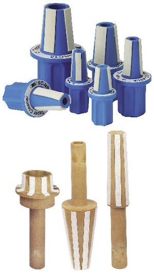
Alpha Taper Internal Toolholder Cleaner and Tekusa Spindle Cleaners
With the machine door closed, chip fans offer a safe way to clean surfaces without operator interaction. This keeps all chips and coolant inside the enclosure, where they can be processed. Benchtop- or tool cart-mounted tool-assembly devices facilitate assembly and adjustment of all types of toolholders. A properly designed tool-assembly device grips the toolholder without damaging surfaces while leaving it exposed for attachment or adjustment of retention knobs, coolant tubes and inserts.
In addition to protecting tool quality, these devices provide safe and rapid tool assembly. Shops should look for tool-assembly devices that allow convenient access for all tooling maintenance operations in one setup, which minimizes tool setup time associated with the assembly and disassembly of tapered V-flange tooling, short-taper tooling, such as HSK and Capto, and modular tooling.
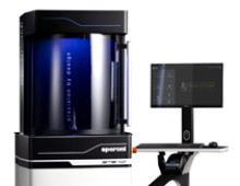
Offline tool presetters are excellent tools for locating and removing runout from tool assemblies. They are also the best way to set tools to specific lengths. Tool presetters can inspect and measure all tool geometries. In lieu of offline presetting, probing systems can be installed in the machine to measure and monitor tool lengths.
Managing Workspace
Some companies experience long downtime as workholding devices are changed at the machine. Use of a repeatable positioning and clamping system for workholding devices can reduce this unproductive time to a few minutes.
These workholding solutions provide fast, accurate and rigid positioning and clamping of workholding components at predefined locations in the machine tool, reducing the time needed to accurately position and clamp a vise fixture.
Grid plates are one of the most common quick-change machine table setup systems. They provide a repetitive series of accurate bushing locations that accept positioning pins to locate a workholding device or workpiece. These positioning locations are intermixed with threaded locations to attach clamps that hold the workpiece or workholding device with sufficient rigidity.
Zero-point clamping systems combine positioning and clamping in a single process (see photo on page 74-S). A retention knob with a geometric reference datum is appended to the workholder or workpiece. The clamping process draws the retention knob into a ground reference that allows for simultaneous positioning and clamping. A single retention location can address small work spaces. Multiple clamping locations can address larger components.
Shuttle tables are track mechanisms connected to the machine table. One workholding table can be shuttled out of the machine and a second table can be shuttled into the machine to enable faster changeovers and minimize downtime between jobs.
Once a machine is purchased and leaves the controlled facility in which it was manufactured, the shop environment influences the machine in many ways. Factors such as ambient temperature, the type of material being cut, operator knowledge, shop cleanliness and air quality make each setting unique. Shops can protect their investment, ensure machine longevity and maximize performance by scheduling regular maintenance checks and by identifying and fixing minor problems before they become major issues.
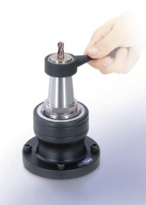
Kombi Grip Tool-assembly Device
Because certain small variables are typically not modeled and debugged by CAD/CAM systems, shops must monitor and manage them to produce reproducible results. Specifically, attention should always be paid to the machine spindle, toolholder assembly and machine table work space.
These unaddressed variables can wreak havoc with form and position tolerances, feature size and surface finish. Because CAD/CAM systems typically do not consider machine spindle or toolholder runout variables, cutter performance can be affected. A preventive maintenance schedule can minimize such problems.
Process Examination
Beyond machine maintenance and upkeep, shops should evaluate their manufacturing processes to identify areas that may be slowing production. In addition to machine speeds and feeds, part cycle time and the time required to pass first-article inspection are crucial—particularly when batch sizes are decreasing.
Unilock ESM 138 Zero-point Clamping System
Manual operations often create the biggest production bottlenecks. And, while many processes require operator interaction, shops must find ways to minimize manual operations associated with tool and machine setup. Strategic use of machine tool accessories can help shops achieve this goal.
Originally published in
Categories
Did you find this interesting or helpful? Let us know what you think by adding your comments or questions below.
Add new comment