

Latest Posts

Mitigating Vibration in Long-Reach 5-Axis Airframe Pockets
Key Points
-
Learn how excessive tool overhang contributes to vibration, chatter and poor surface finish in deep aerospace pockets.
-
Understand how 5-axis machine geometry creates clearance challenges and increases the risk of tool deflection and premature tool failure.
-
Discover how tapered tool holders and vibration damping technology can improve machining stability, surface quality and tool life.
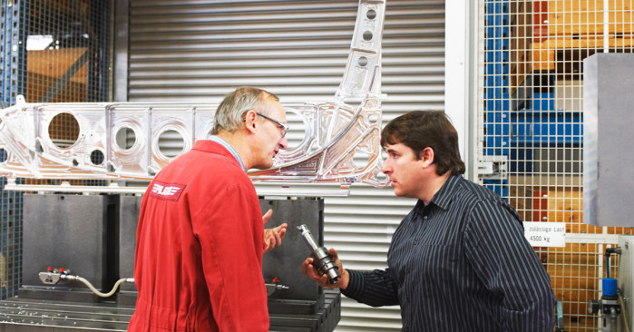
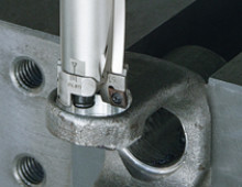
Modern aerospace airframes are engineering marvels, and one of the most complicated parts to machine. The structural logic that makes them strong also makes them extraordinarily difficult to cut. Deep, narrow pockets are machined into wing spars, bulkheads and fuselage frames to reduce weight while preserving load-bearing integrity. These features are often hundreds of millimeters deep, steeply walled, and accessible only through a tight opening that barely accommodates the cutting tool, let alone the tool holder and spindle head articulating it.
This is where 5-axis machining creates a paradox. The same multi-axis capability that allows a machine to reach compound angles inside an airframe pocket simultaneously restricts how much tool body can be positioned near the spindle. To clear the space taken up by the 5-axis head and still reach pocket depth, machinists are forced into extreme tool overhang, which introduces vibration.
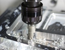
This paradox shows up as chatter marks on pocket walls or a subpar surface finish that doesn’t pass first article inspection. On the tooling side, premature cutter and/or insert failure causes tooling costs to soar. The nightmare result is a scrapped titanium billet worth tens of thousands of dollars. Solving the problem requires understanding what vibration is, where it comes from and how tooling geometry can be used to move that problem out of the cut.
Understanding Tool Overhang and Why It Destroys Aerospace Pockets
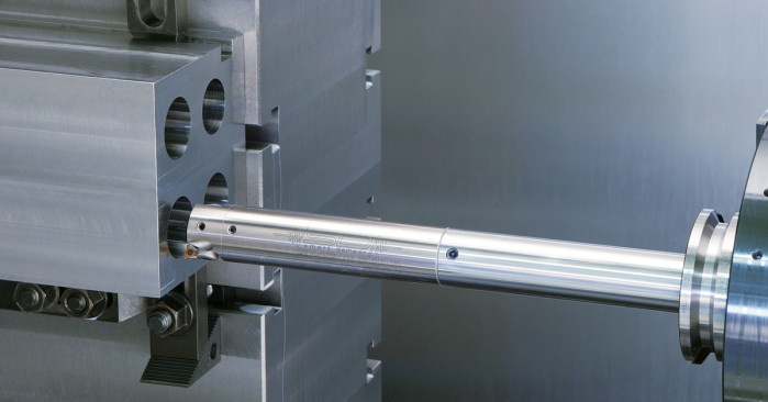
Tool overhang is the distance between the last point of rigid support (the spindle or holder contact) and the cutting edge. In standard milling applications, keeping the overhang to tool diameter ratio below 3:1 is a baseline rule of thumb for maintaining stability. In 5-axis airframe pocketing, ratios of 8:1 or higher are common. At those lengths, the tool assembly stops behaving like a rigid cutting instrument and starts behaving like a tuning fork.
The physics are straightforward. Deflection under cutting load increases with the cube of overhang length. Double the overhang and you don't double the deflection; you actually multiply it by eight. At the same time, the natural frequency of the tool assembly drops as overhang increases, making it far easier for cutting forces to excite resonance. Once the tool is vibrating in harmony with its own natural frequency, chatter becomes self-sustaining. The cut amplifies the vibration rather than damping it, and surface finish deteriorates rapidly.
What makes this particularly damaging in airframe machining is the material. Titanium and aluminum alloys used in structural aerospace components are unforgiving. Titanium in particular has a low thermal conductivity that concentrates heat at the cutting edge, and any vibration that disrupts chip formation also disrupts heat evacuation. This results in accelerated tool wear, microstructural damage to the workpiece surface and dimensional error that can compromise the pocket's function as a stress-carrying feature.
How the 5-Axis Head Worsens Vibration
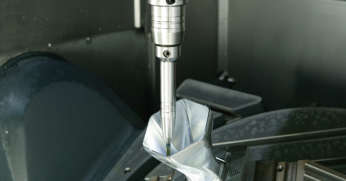
In a standard vertical machining center, you have relatively free choice over holder length and shank diameter. In a 5-axis configuration, the rotating head adds a fixed geometric constraint. The head itself has a minimum clearance envelope that the holder must clear during articulation. That envelope effectively sets a floor on how far the tool must extend below the spindle face before it can even enter the pocket. You're starting the overhang calculation from a deficit before the cut begins.
The instinct in this situation is to reach for a longer, thinner extension. More length will clear the head, and reduced diameter will fit the pocket opening. In reality, this is almost always the wrong call. Length adds deflection exponentially and reducing diameter drops stiffness further. You've compounded both variables in the wrong direction.
The correct response is to address the pivot point of vibration, which is the location along the tool assembly where the bending moment is highest and where vibrational energy is most efficiently amplified. This is where tapered tool holders change the equation.
Shift the Vibration Pivot Point in 5-Axis Pocketing with Tapered Tool Holders
A straight cylindrical extension has a uniform cross-section along its entire length. That means the bending stiffness is constant from holder to tip, and the pivot point (the location of maximum deflection under lateral cutting load) sits close to the cutting edge.
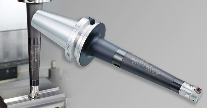
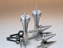
A tapered-body holder changes this geometry fundamentally. By concentrating mass and cross-sectional area toward the spindle end and reducing diameter progressively toward the pocket, a tapered holder raises the natural frequency of the assembly and pushes the pivot point away from the cutting edge and back toward the spindle. The physics work in your favor, since more of the assembly's mass is located at the supported end rather than at the unsupported tip. This creates a stiffer effective assembly at the same nominal reach, with a natural frequency that is higher and harder for cutting forces to excite.
In 5-axis pocketing specifically, this matters because the taper also addresses the clearance problem. A well-designed tapered holder can provide maximum diameter near the spindle while slimming down precisely where the pocket geometry demands it. You get clearance and stiffness from the same geometry, rather than trading one for the other.
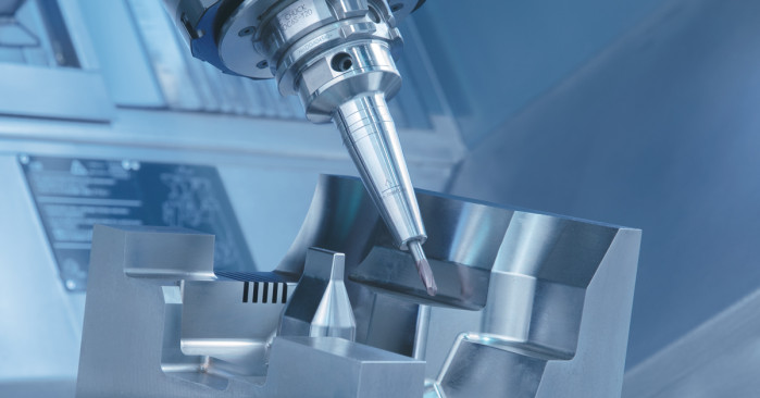
Paired with vibration damping technology, such as the BIG DAISHOWA Smart Damper system, which uses a tuned internal mass to absorb vibrational energy across the tool assembly, tapered holders allow machinists to push deeper into airframe pockets at practical metal removal rates without sacrificing surface integrity or tolerances.
Ensure Stringent Vibration Damping During Airframe Machining with BIG DAISHOWA Precision Tools
No single product eliminates chatter in a challenging 5-axis airframe application. The solution is a connected system: the right holder geometry, the right damping technology, the right collet interface and a clear understanding of where the vibrational energy is being generated and absorbed at each point in the assembly.
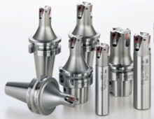
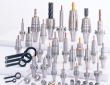
The BIG DAISHOWA line of tapered holders, damping bars and modular tooling components is engineered specifically for the constraints of high-stakes aerospace machining. If your operation is fighting vibration in deep airframe pockets, the answer lies in smarter tooling geometry.
How can we reduce scrap and save time in your airframe tool holder setup? Contact us today to explore solutions for your operation.
Categories
Did you find this interesting or helpful? Let us know what you think by adding your comments or questions below.


Add new comment